AGUAR WATER TECHNOLOGIES LLP
AGUAR WATER TECHNOLOGIES LLP
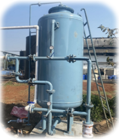
Media Filtration System
In media filtration process fluid flows down wards through the filter bed and suspended matter/turbidity is retained on the filter bed. There is steady rise in the loss of head over a period of time and the flow reduces once the pressure drop across the filter is excessive. The filter is then taken out of service and cleaning of the filter media is effected by flow reversal also called as backwash. To assist in cleaning the bed, the backwash operation is sometimes preceded by air scouring by way of agitation through the under drain system. The air scouring agitates the media with a scrubbing action, which loosens the intercepted particles. The filter is ready to be put back into service after backwash.
1. Pressure Sand Filter (PSF):
PSF is designed to remove turbidity and suspended particles present in the feed water with minimum pressure drop. These Filters are custom designed to suit the process requirement. These filters are offered in Mild Steel, FRP or SS construction with frontal piping and associated valves.
2. Activated Carbon Filter (ACF):
ACF are designed to remove free chlorine, organic matter, odour and colour present in the raw water and effluent. Activated carbon filter operates through adsorption. Adsorption is directly related to the surface area of the media. Activated carbons provide a large surface area due to its high degree of micro porosity. The Activated Carbon Filters consist of Activated carbon granules supported by very fine quartz filter media.
3.Glass Media Filter, Filter media:
Activated Glass Media Filtration is advance filtration over traditional sand media or multi-grade filtration. Glass media is a specific type glass, has optimum particle size and shape, and activate surface area. The high surface area is charged to attract organics and small particles.
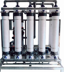
Membrane System
Ultra Filtration System:
• Ultrafiltration plants have been extremely useful in water and wastewater treatment. Ultrafiltration systems utilize hollow membrane fibers.
• It is a pressure-driven membrane separation process that removes suspended or particulate matter (including colloids & silt) from water.
• Pumps send the treated water through microscopic pores, which act as a physical barrier that only allows filtrates to pass through them.
• It is more reliable than conventional multimedia filtration that removes particles of 10 microns in size or larger.
• It also efficiently removes bacteria and most viruses
• After UF treatment, the water can be sent to a reverse osmosis system for further purification or can be used.
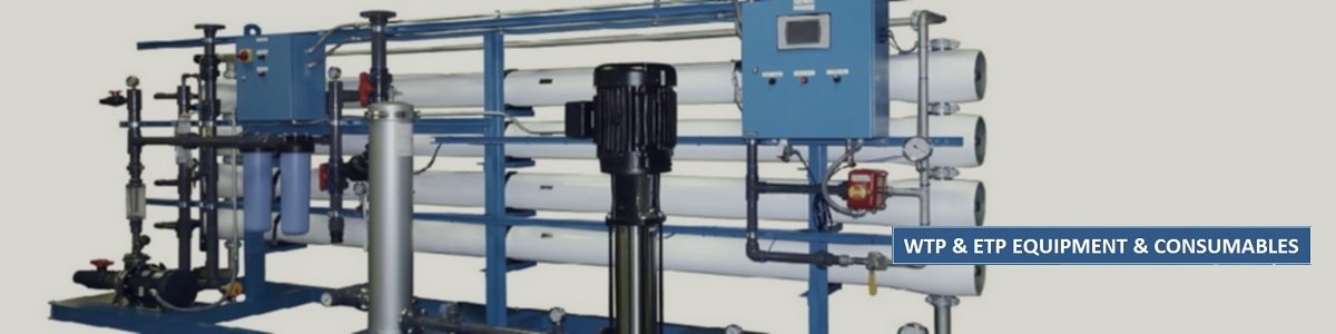
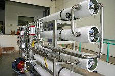
Reverse Osmosis System
• Reverse osmosis is a water purification process that uses a semi-permeable membrane to filter out dissolve salt and impurities from water.
• Reverse osmosis systems work by applying a high pressure pump to a concentrated solution of unfiltered water, which can be in the form of seawater, brackish, supply water or wastewater.
• The system forces the water through a semipermeable membrane, leaving virtually all of the dissolved salts and other substances behind.
• RO Plants work on the Crossflow Filtration method, which takes the feed water and uses a percentage of it as a wash or reject stream, removing the solids during the filtration process.
• Pretreatment is necessary when working with reverse osmosis systems to protect the membranes from fouling and failing prematurely.
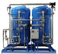
Softener plant
• A water softener plant is designed to remove positively charged ions of calcium and magnesium from water. It is essential to treat hard water in industries as it can cause expensive machinery and equipment to malfunction. As positive and negative ions get stuck with each other, hard water flows through resin beads, becoming soft, and this soft water comes out through its outlet. The softener plant can be in the form of an automatic, semi-automatic, or manual version.
• Resin is the ion exchange media used commonly in water softening applications. The most widely used resin in the industry is polystyrene-type gel resin. This resin has a very porous, skeletal structure and each bead ranges in size from 0.3-1.2 mm, containing approximately 45% moisture.
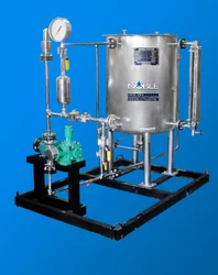
Chlorine Dioxide System
• The chlorine dioxide generator system is designed considering the all related aspects. The system consists of skid mounted chemical dosing pump to feed the required quantity of the chemicals and properly designed generator, where the reaction of this two precursor will take place.
•Filtered water of controlled flow rate of about 1 m3/hr. is given in the reactor.
•The gas will be generated in the specially designed reactor. This gas with water mixture will be applied to use points.
•The system consists of Precursor Feed Pumps, Chlorine dioxide Generator, Dosing tank for acid, Dosing pump for acid, Dosing tank for CP-2200, Dosing pump for CP-2200, Rotameter & ORP meter.
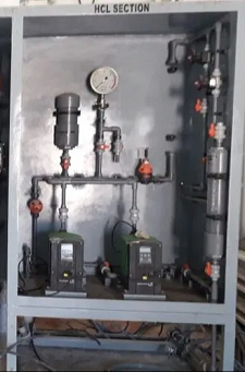
Chemical Dosing Unit
The chemical dosing process treats water and wastewater to remove its impurities with high levels of chemicals dissolved into it like aluminium, iron, chlorine etc. A dosing system is designed to release chemicals at a certain pressure and speed into the water, depending on how much of chemicals are dissolved in the wastewater coming through the inlet. The chemical dosing unit consist of dosing tank, agitator/mixing system, dosing pump and its piping & electrical.
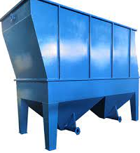
Tube Settlers
• Tube settlers increase the settling capacity of circular clarifiers and/or rectangular sedimentation basins by reducing the vertical distance.
•The floc particles would settle before agglomerating to form larger particles. The settlers use multiple tubular channels sloped at an angle of 60° and adjacent to each other, which combine to form an increased effective settling area. This provides for a particle settling depth that is significantly less than the settling depth of a conventional clarifier, reducing settling times.
•Tube settlers capture the settle able fine floc that escapes the clarification zone beneath the tube settlers and allows the larger floc to travel to the tank bottom in a more settle able form. The settler's channel collects solids into a compact mass which promotes the solids to slide down the tube channel.
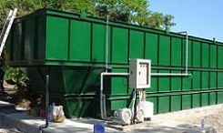
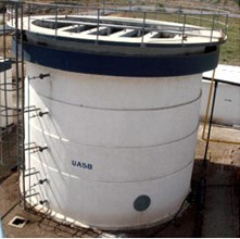
UASB Reactor
Up-flow anaerobic sludge blanket (UASB) reactor belongs to high-rate systems, able to perform anaerobic reaction at reduced hydraulic retention time, if compared to traditional digesters. The UASB reactor is designed for specific COD loading and hydraulic throughput.
A flow distribution network is located at the base of the reactor to distribute the flow evenly throughout the bottom of the reactor. New bacterial cells formed in the reactor aggregate into tiny flocs with extremely good settling characteristics. The biogas produced by the bacteria in the form of small bubbles, rises upward through the sludge bed/blanket zones and provides a natural mixing action. When the biogas reaches the top of the reactor, gas collectors remove it. Rising effluent will overflow from gutter into the launder. Part of the UASB outlet shall be recycled to Homogenization Tank for conditioning of raw effluent and part will flow to the subsequent treatment unit. Sludge will be taken to the sludge handling system.
MBBR system
MBBR is commonly known as Moving Bed Biofilm Reactor, is a type of wastewater treatment process. MBBR is a highly effective biological treatment process based on a combination of conventional activated sludge process and biofilm media. The MBBR process utilizes floating media within the aeration and anoxic tanks. The microorganisms consume organic material. The media provides increased surface area for the biological microorganisms to attach and grow. The increased surface area reduces the footprint of the tanks required to treat the wastewater. The treatment process can be aerobic and/or anaerobic and operates at high volume loads.